Choosing a diesel fuel purifier starts with the duty it must perform: protecting fuel on its way to equipment, or taking part in a tank-circulation system. Confirm the fuel condition and the actual flow through the purifier before comparing the five Dieselcraft models. This guide gives you the decision path and the tables to check it against the manufacturer’s data.
Quick pick: which model fits your duty?
| Your duty | Choose | Why |
|---|---|---|
| Compact installation; stationary pump, generator or equipment; up to 15 GPM | 5×16 | Compact 5-inch unit, 15 GPM maximum flow; stated engine range 400 to 1,200 HP |
| Circulation pump rated 4 to 7 GPM; room for a longer vessel | 5×24 | 5-inch unit, 20 GPM maximum flow, 1 in. connections; stated engine range 600 to 1,500 HP |
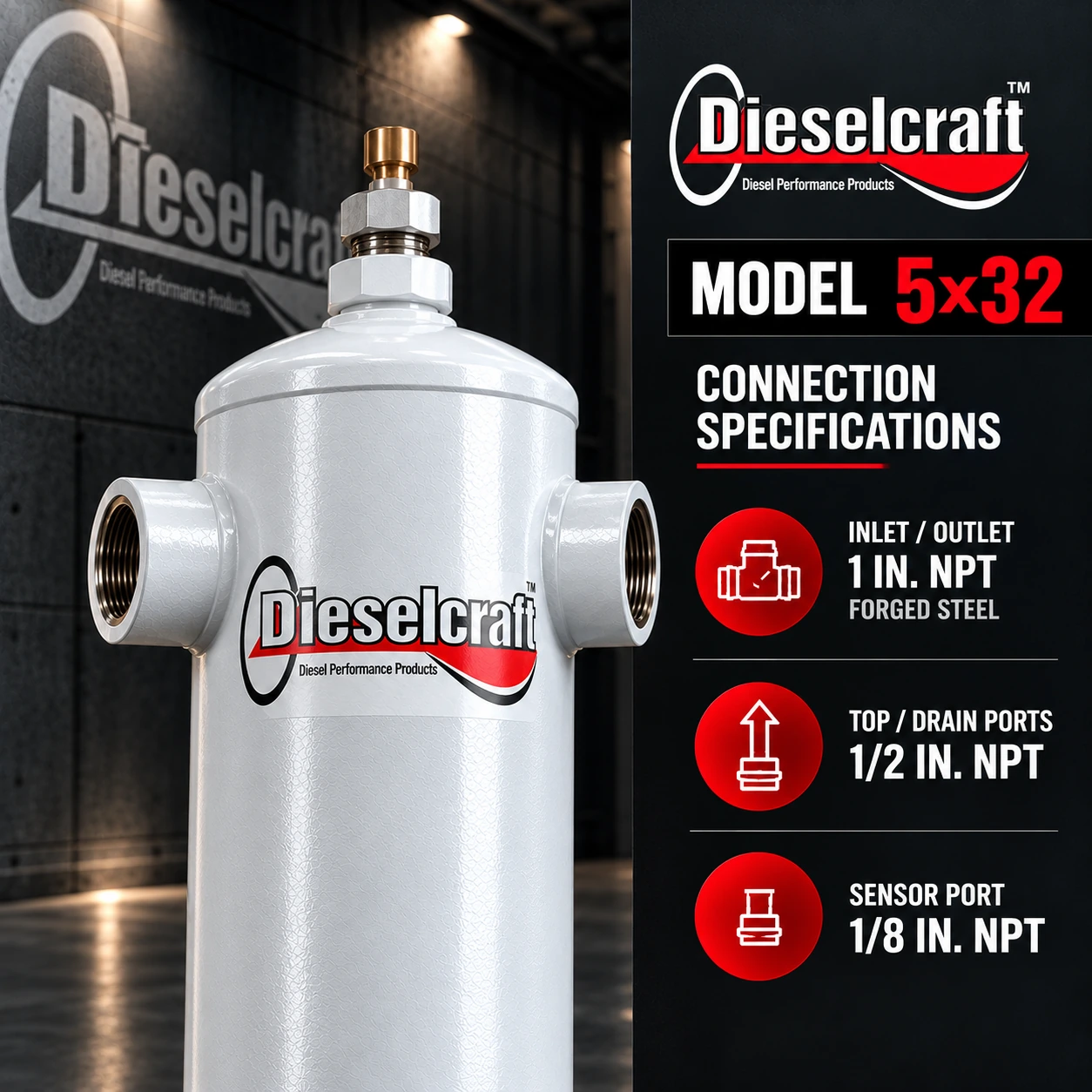
| Pumps rated 8 to 18 GPM; you want the longest residence time in the 5-inch family | 5×32 | 5-inch unit, 18 GPM maximum flow, 35.86 in. tall; stated engine range 600 to 1,500 HP |
| Larger installations: gen sets, locomotives, fuel docks, up to 25 GPM (1,500 GPH) | 8×30 | 8-inch unit with 2 in. connections; includes mounting strap, 06-5 water sensor and drain valve |
| The largest flows: stationary pumps and fuel docks, up to 40 GPM (2,400 GPH) | 8×51 | 8-inch unit with adjustable legs and mounting hardware supplied |
Step 1. Define the job before choosing a model
Record the application: standby generator, stationary pump, marine installation, transfer line or fuel dock. For bulk stored-fuel cleanup, assess the complete polishing arrangement, including pumping, tank access and downstream filtration. A purifier is a component of that arrangement; its model number alone does not define tank-cleaning capacity. See How to Choose a Diesel Fuel Polishing System for that case.
Step 2. Use actual line flow, not engine consumption alone
Ask for the pump flow through the proposed installation point, including any circulating or return fuel. Record normal and peak flow in GPM or L/min. Engine horsepower is supporting context, not a substitute for this information. Compare the flow with the maximum flow of each model:
| Model | Maximum flow | In GPH | Best fit (manufacturer data) |
|---|---|---|---|
| 5×16 | 15 GPM | 900 (calculated) | Stationary diesel pumps, generators and equipment; 400 to 1,200 HP |
| 5×24 | 20 GPM | 1,200 (calculated) | Circulation pumps rated 4 to 7 GPM; 600 to 1,500 HP |
| 5×32 | 18 GPM | 1,080 (calculated) | Pumps rated 8 to 18 GPM; 600 to 1,500 HP |
| 8×30 | 25 GPM (95 L/min) | 1,500 | Stationary pumps, gen sets, locomotives, fuel docks; 1,200 to 2,000 HP |
| 8×51 | 40 GPM (151 L/min) | 2,400 | Stationary pumps, fuel docks and equipment; 1,200 to 2,000 HP |
Step 3. Compare the five models
All figures are from the Dieselcraft product portfolio. Click a model to open its product page.
| Model | Inlet / outlet | Size | Weight | Finish | Notes |
|---|---|---|---|---|---|
| 5×16 | 1/2 in. NPT, forged steel | 5 in. dia. × 17.8 in. | 15 lb (6.8 kg) | White epoxy powder coat | Compact high-flow |
| 5×24 | 1 in. NPT, forged steel | 5 in. dia. × 25.48 in. | 18 lb (8.2 kg) | Gray epoxy powder coat | Mid-length |
| 5×32 | 1 in. NPT, forged steel | 5 in. dia. × 35.86 in. | 20 lb (9.1 kg) | Gray epoxy powder coat | Maximum residence time |
| 8×30 | 2 in. NPT, forged steel | 8 in. (203 mm) × 31.93 in. | 40 lb (18 kg) | Gray epoxy powder coat | Includes mounting strap, 06-5 water sensor, drain valve |
| 8×51 | 2 in. NPT, forged steel | 8 in. (203 mm) × 31.93 in. vessel; port height with legs 42.6 to 46.6 in. | 68 lb (31 kg) | Gray epoxy powder coat | Adjustable legs and mounting hardware supplied |
Common to all five: filterless operation, vertical installation, bottom drain, a five-year warranty as listed by Dieselcraft, and removal of 99% of water and 95 to 98% of heavy particles.
Step 4. Understand separation and its limits
Dieselcraft describes this product line as filterless separation of free water and heavy contamination. Fine suspended solids and emulsified water require a suitable downstream treatment strategy. Keep the engine manufacturer’s required filtration in place. Removal of water or visible debris does not, by itself, establish complete fuel quality or eliminate active microbial growth.
- Fuel enters the vessel at the inlet.
- Long residence time and the proprietary media let free water and heavy particles separate out.
- Cleaner fuel leaves through the outlet toward the engine filtration.
- You drain the collected water and sediment from the bottom drain.
Step 5. Check the installation before ordering
| Check | What to confirm |
|---|---|
| Fuel and compatibility | Diesel only. The 8×30 and 8×51 are marked not for use with gasoline. |
| Line flow and conditions | Normal and peak flow, line pressure and operating temperature. |
| Connections | Inlet and outlet size: 1/2 in. for the 5×16, 1 in. for the 5×24 and 5×32, 2 in. for the 8-inch models. |
| Space and support | Height, diameter, mounting and support. Units install vertically; the 8×51 sits on adjustable legs. |
| Access | Room to drain from the bottom drain and to inspect; sensor access if you use one. |
| Downstream | Existing downstream filters and equipment requirements. |
Mounting strap, sensor strap, tripod-leg and water-sensor options are listed for the 5-inch models in the Dieselcraft portfolio; ask us to confirm what applies to your installation.
Nine tips from the field
- Measure the real pump flow before you look at models.
- Keep the engine’s own filtration in place after the purifier.
- Drain the collected water on a schedule set by the contamination load.
- Record what you drain: volume of water and amount of sediment.
- If contamination keeps coming back, look for the source, such as tank breathing or a leaking seal.
- Test the fuel after corrective work to confirm the result.
- Do not size by engine horsepower alone.
- Mount vertically with room under the drain.
- Check the current data sheet for your exact model before you order.
Five mistakes to avoid
- Sizing by horsepower alone. Use the pump flow.
- Choosing the longest vessel for the highest flow. They are different things.
- Treating a purifier as a tank-cleaning system. A tank needs a full polishing arrangement.
- Removing the engine filters. The purifier does not replace them.
- Skipping the verification test. Water removal alone does not prove fuel quality.
Send us a useful selection brief
Provide the equipment and pump models, fuel type, normal and maximum flow, line pressure, connection sizes, available dimensions, operating schedule and photos or a line sketch. Add the tank volume and cleanup objective if the purifier will be part of a polishing loop. Start from our Fuel Purification solutions or contact ANKORZ directly.
Frequently asked questions
Does a Dieselcraft purifier use filters?
No. These are filterless purifiers. They separate free water and heavy contamination without a replaceable, changeable or cleanable filter element, so there is nothing to change inside the purifier. You drain the collected water and sediment from the bottom drain.
Is a purifier enough to clean a stored-fuel tank?
Not on its own. A purifier is one component of a polishing arrangement that also needs pumping, tank access and downstream filtration. For tank cleanup see our guide on choosing a diesel fuel polishing system.
Can I use these purifiers with gasoline?
No. The 8×30 and 8×51 are marked not for use with gasoline, and the whole range is for diesel.
How do I pick the size for my pump?
Start from the actual pump flow at the installation point, in GPM, then compare it with each model’s maximum flow in the table. Engine horsepower is supporting context only. Confirm the final choice against the current Dieselcraft data sheet.
What warranty do the purifiers have?
Dieselcraft lists a five-year warranty for the range. Confirm the current terms for your model with ANKORZ before ordering.
Related reading
- How to Choose a Diesel Fuel Polishing System
- How to Choose a Fuel Test Kit
- The Complete Guide to Diesel Fuel Contamination in the GCC
- Do Chemical Fuel Additives Remove Water From Diesel?
Source: Dieselcraft product portfolio, Fuel Purification section. GPH figures marked calculated are GPM × 60. Consult the current technical data sheet for the exact model before final selection.